Trial by Aftermarket ECU
These are the ups and downs of the past few days.
Multiply this by a month and you will get the picture of how agonizing this whole Simplify My Life with an Aftermarket ECU project has been.
I do think this will be a net benefit in the long run. But it would have been a lot simpler if someone had made a complete blog post about installing a Microsquirt ECU in a NA6 Miata based kit car for my reference before I started. So for the benefit of anyone insane enough to follow in my staggering footsteps, I'm going to post all my hard-earned knowledge here.
The Big DO NOTs
DO NOT use a cheap no-name main circuit breaker. Yes, the one from Bussman costs 3x as much. It is worth every penny.
DO NOT try to use ANY serial adapter other than the one sold by the actual Microsquirt people. It's not that much more expensive and it has the magic fairy dust needed to make everything actually work.
The Great TPS Conundrum
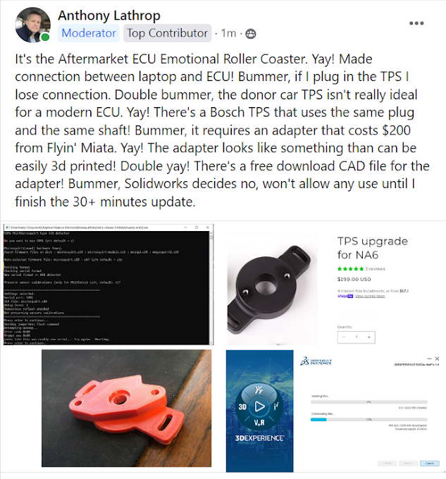
At one point I had the ECU and laptop on speaking terms with each other... but only if I had the throttle position sensor unplugged. It turns out that the early Miata 1.6 L / NA / Mk1 manual transmission TPS isn't really a throttle position sensor. It's a switch with three positions: off, idle, and full throttle. Word on the street is that this can be made to work with the Microsquirt ECU, but it has to be wired differently or else it shorts out the 5 volt reference supply and makes the ECU go incommunicado. The automatic trans NA6 has an actual variable TPS - but - it isn't compatible with the manual transmission throttle body. A third option is to retrofit a modern TPS as noted above. Some say this is only necessary if you're going to use a turbocharger, a supercharger, or individual throttle bodies, or if you have somehow offended the Patron Saint of Engine Sensors in the past and filled him with vengeful rage. Others - including the people who sell the Microsquirt - say that the true variable TPS is better, absolutely necessary, and/or the Key to Inner Peace. So I went with this advice and started working on fitting a modern Bosch TPS to my 1992 Miata throttle body.
The free download TPS adapter shown above was just not at all attractive looking so I CAD'd my own styled after the design of the one from Flyin' Miata.

The lure of 3d printing is the promise of instant gratification: think it, CAD it, make it real... all in short order. But sometimes it's not that simple. PLA plastics are 3d printer friendly and it's relatively easy to get a clean print. But PLA isn't very strong and doesn't keep its shape in high heat. It's great for temporary parts like a drill guide or or a fiberglass mold - but if you want to 3d print an adapter, install it in an engine bay, and not have it melt you'll need to use ABS. ABS is much less gooey and has a much higher melting point, which is great for the finished part but not great for the 3d printing process. The part shown above right was the 3rd or 4th attempt. It's not perfect but it should work, and will probably look presentable after sanding and spray painting.
Progress, Setback, Diversion, Progress
So I got (the aftermarket copy of) the Bosch TPS and had it working, on the dismounted throttle body, for a while. But the Bosch TPS orients at a different angle and the OEM wiring connector is humongous, and there's a vacuum line in just the right place for it not to fit. I tried to "modify" (heat and bend) the connector, and thought I had made it fit... but not quite, and broke the TPS when I tried to reinstall the throttle body. So I had to order another one and wait. In the meantime I dispersed frustration by catching up on a few lingering jobs.

Above left: Need a radiator catch can before starting the car, and finally got around to installing it. Not the most elegant part nor the most elegant installation, but serviceable. And the bodywork will obscure some of this from above.
Above middle and right: I had the exhaust (mostly) installed but it lacked lateral support and probably would have clanged against the differential often enough to become an annoyance. I wasn't sure how I was going to fix this but then saw a spot on the rear subframe where I could mount an exhaust hanger laterally to stabilize the side-to-side movement. This is an entirely DIY hanger and other than the messy welding between a plate and a rod (which is legitimately tricky) I think this came out pretty well. It does extend lower than it needs to... I could dismount it, cut off the excess, re-bend the rod, and repaint the resulting paint damage. Or, I could just leave it. Yes, I realize the left rear lower A-arm alignment bolt is not situated properly in its recess.
By this time I'd gotten the new TPS and some new wire terminals smaller than anything I previously had used. Since there wasn't room for the OEM wire connector I had to improvise something.

Above left: If you're going to get a terminal crimper, get the one with interchangeable jaws to fit the terminals you're using precisely. Left and middle: there is something primordially satisfying about a crimp terminal that turns out well. Right: this shows how much longer the OEM wire connector (above) sticks out compared to my DIY terminals directly mounted to the tabs inside the socket.

Above: Bosch TPS mounted on to my 3d printed adapter, itself mounted on the throttle body. You can see to the right of my wire connectors how little space there is between the TPS socket and the vacuum line. It is not visible from this angle, but I used clear silicone to fill the socket and hopefully keep the crud out of there. I am a late-stage fastener nerd, and cannot pass up any opportunity to use acorn nuts. I am also fond of flange head nuts and screws (mounting the adapter to the throttle body). Yes, I have favorite fasteners. A DIY car is a good project from someone who has favorite fasteners.
After four weeks of desperate thrashing, the above was a memorable milestone. Finally, the sensors are communicating with the ECU and the ECU is communicating with the laptop - as evidenced by the throttle position indicator reflecting my opening and closing the throttle (off screen).
I entered all the ECU settings specific to the 1.6L/NA6/Mk1a motor and the calibrated the sensors - mostly OEM Mazda, but I am using a 3-bar GM MAP sensor and a GM IAT sensor in lieu of the motor's original MAF setup with its 12 cubic meters of ductwork. In theory this provides better data to the ECU. The theoretical fraction of a horsepower this could yield is not very important to me, but tidying up the engine bay is one of the core values of my faith.
Up next there are still several steps to go through in the First Engine Startup process. I'll update on these as I go, to keep all the ECU-specific info in this one post.
Also of note in the past few weeks, Taylor the Mighty got the Pops Racer go kart going again, after it sat in the barn for 35 years or so. She got a little bit of help from her dad, but really not much. I had a full pro racing shop and Pops' pro level teaching as a kid, while Taylor has DIY dad, the tools in our garage, and only sporadic access to Pops and his shop - but still she's miles ahead of where I was when I was 13 years old. She demonstrated and developed a lot of skills in the go-kart project, but I am most proud of how she kept plugging away at the many not-glorious tasks and nontrivial number of setbacks and frustrations. The broccoli-to-dessert ratio of this project was very unfavorable for a 13 year old but she persevered and was rewarded with success.
Comments
Post a Comment