There is a balance in any large project between forcing jobs forward when the preconditions and resources aren't fully sorted (which often ends poorly) and allowing the project to stagnate (which often ends poorly). There was only very slow progress through December 2024 and January/February 2025 - partly due to family and work, another big project underway, and viciously cold weather. My garage doesn't have any effective heating. When it's 35 F or higher I can dress for it or use a local area heater and work quite happily - but when the daytime high is 12 F I will have a very difficult time convincing myself to go to the garage, much less stay and work there. Not to mention, some jobs can't or shouldn't be done below a certain temperature (see below).
But now the weather is starting to warm up and I feel like the sports car project is starting to regain some momentum.
Re-do #1
I used the redneck pre-preg method to lay fiberglass in attempt #1 to make the mold for the fuel cap recess area. The pre-preg wasn't as mess-free as some people make out (could be user error) but it was a lot less messy than the willy-nilly way I used to lay up fiberglass.
The good news: my newly-learned tricks for spraying PVA worked well, and it's wasn't a nightmare to get the mold off.
The bad news: I was working in the cold and I didn't give it it enough curing time, which created some irregularities when soft spots cured without the plug there to hold their shape. Also, I realized I need a larger flange around the recess. And, I forgot my father's favorite trick - bonding strips of wood in to the mold to stiffen it and give something to grab hold of when you're trying to pull the mold off the plug.?
The biggest difference between old guy me and young guy me: young guy me would have been upset about this, seen it as a delay, and tried to use the flawed mold. Old guy me realizes he'll save himself a ton of trouble with a re-do. Besides, this is a hobby that I enjoy, so what's the big problem having to do more of my hobby? It only took me 45 or 50 years to figure this stuff out. Welding
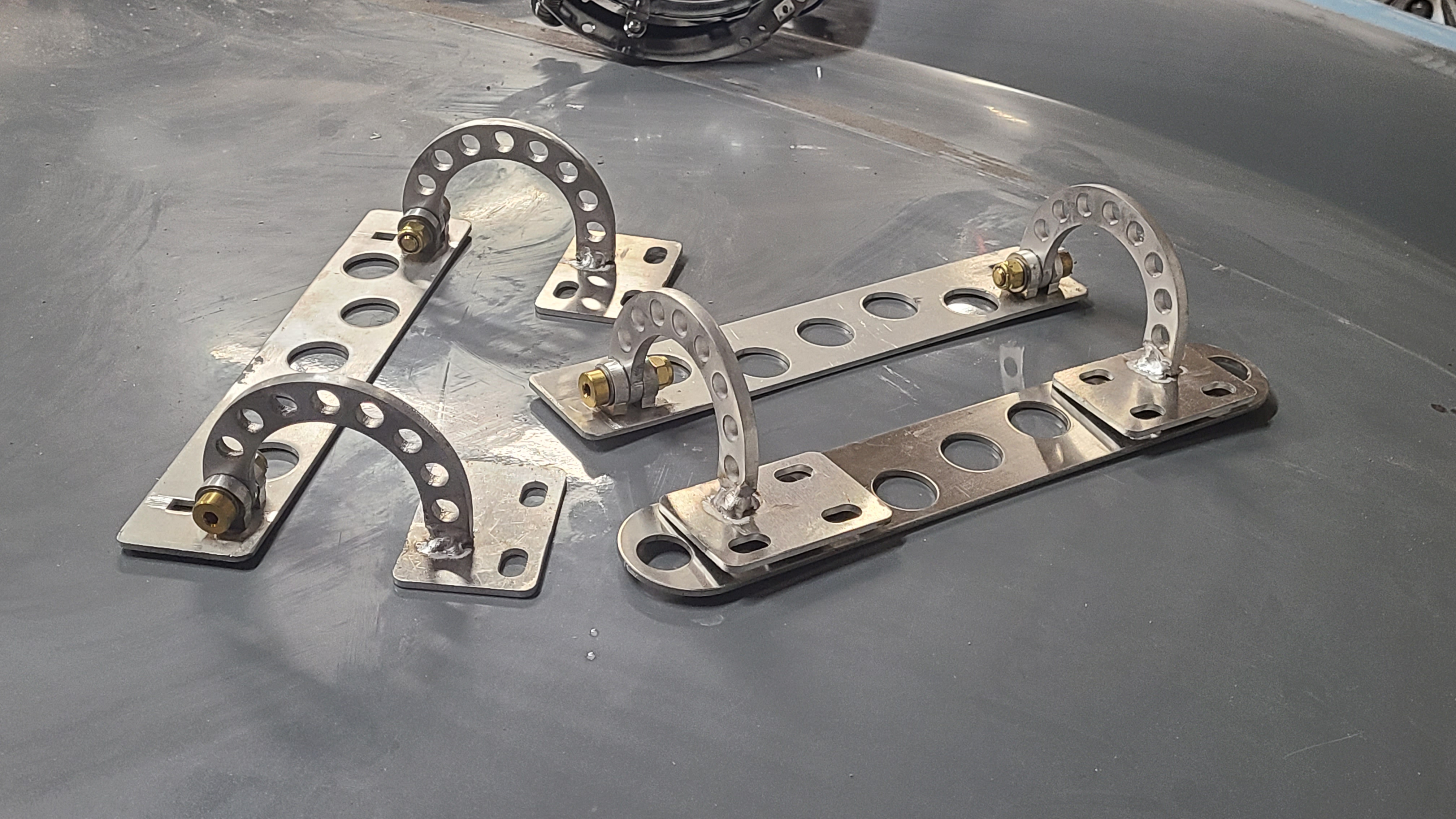
These are the hinges for the trunk/boot and bonnet/hood. I used a piece of 3/8" steel rod to ensure alignment of the hinge pivots and welded the hinge pivots in place from behind.
I did not cover myself in glory with this welding job. It's an alloy of aluminum that doesn't just love to be welded. The welds are all inside corners. The material is thick compared to its length so as soon as you get going you're on the verge of melting a corner off.
The more I try to weld, the more I appreciate how great a welder my father is. I have gotten to the point that I can produce a serviceable weld fairly reliably. When I was a kid I remember my father routinely welding things that people said could not be welded, and doing an artist-level job of it.
Above: Welded and assembled. On the right side pair, the underlying stainless steel plate gets tapped for 8mm studs then bonded in to the bodywork with fiberglass. Then the hinge assembly bolts on to the studs, with slightly oversized holes to allow adjustment of the alignment. The aluminum plates on the opposite side get bonded directly in to the bodywork. You may notice there is a missing stainless plate in the above picture.
The most reliable way to find something is order a replacement for it. No sooner do I get the Send-Cut-Send notification "your order is in production" than I instantaneously find the missing backing plate.
Above left: No, I am not experimenting with h̶i̶g̶h̶ s̶p̶e̶e̶d̶ t̶a̶p̶p̶i̶n̶g̶ accelerated tap destruction: this is just how I get the tap started straight. Chuck it up in the drill press and turn by hand until it gets difficult. Then switch to my favorite hand tapping tool.
Above right: My favorite hand tapping tool is a 3/8" drive tap holder, a 1/2'-3/8" drive adapter, and a 1/2" drive breaker bar. Much more satisfactory than the inexpensive tap handles and much less expensive than the really good ones.
Mold Attempt v.2
Above: the fuel filler cap recess area is cleaned up, now sanded and finished in an expanded area, and I've started spraying PVA on it in preparation for Mold Attempt V.2
Came out a lot better this time (below:)
There is a little bit of texture from irregularities in the sprayed on PVA release agent, but these are very small and should clean up without too much fuss. I also made the surround large enough this time.
Having produced what promises to be a workable mold, I cut the 3d printed plug out of the fender top. Order of operations: clean up the mold, apply mold release agent, screw into place over this hole. Then, with the body off the car (there are a few more body-on jobs before I get there) I will lay up new fiberglass in this area from below - thus hopefully re-creating the top of the fender only this time with a fuel cap recess in place.
The question naturally arises, why not just leave the 3d printed plug in there and move on? A1: this particular 3d printed plug was PLA+ which does not stand up to the kind of temperatures encountered when a car is left outdoors on a hot sunny day. A2 PLA+ isn't very strong, and probably wouldn't hold up to repeated opening/closing of the fuel cap. To these one might naturally ask, why not just print the part using a stronger 3d printing material? A (the big one): no matter how strong the 3d printed part is, there is no great way to fix it in place - thus creating a likelihood that eventually the joint where the 3d printed part meets the bodywork will either become apparent via cracked paint, or worse, break free entirely. Bonding new fiberglass in place - probably with a layer of Kevlar gapping the new and old fiberglass - will make this area as strong or stronger than the rest of the bodywork.
Cut Holes in Stuff
There are a few more spots where I want to revise the bodywork. I like the look of the Aston Martin badge when it's inset into a recess, thusly:
So I modeled the shape of the badge and made 3d prints that bump out (opposite of a recess), cut holes in the front and rear of the bodywork, and screwed the 3d "bump" shapes into place.
Just as with the fuel cap recess above, I will lay new fiberglass into the hole from the other side - hopefully resulting in a re-creation of the original bodywork contour except with recesses for the badges.
There were also holes to cut for the headlights, grille, and fog lights.
The blue stuff in the picture above is Superfil epoxy filler; sort of a stronger more adhesive Bondo.
Below: working on bezels for the fog lights. I plan to leave these in a matte aluminum finish. Not sure what fasteners to use for these, but I really do like solid rivets so that will be a difficult temptation to resist.

So you've got an irregular round-ish shaped sheetmetal bezel, and you want to cut a similarly irregular round-ish hole in the middle of it. And you want to distribute 6 bolt holes evenly around the bezel. What do you do?

Here's you what you do (above): You put the bezel on your scanner, import it into SolidWorks, and create a spline that matches the round-ish-ness. Then offset the spline by half an inch twice, then distribute a pattern of bolt holes using the middle spline as the path. Then, just as you are about to print out the SolidWorks drawing on paper with the intention to spray mount it on plywood, cut out the inner spline, and use it as a router guide, you remember you have a 3d printer. So you just print the router guide straight from your laptop.

Above: router, router guide, and bezels. I just used a regular router bit with a bottom guide bearing. It cuts through 0.025 aluminum like buttah. Well, like buttah that sprays razor sharp metallic shards of death in every direction. Definitely wear safety glasses / face shield for this. It really does make very clean cuts. I am not sure how this would behave with thicker aluminum.
Each bezel is actually a pair: an outer ring with countersunk holes and an inner ring with riv-nuts.
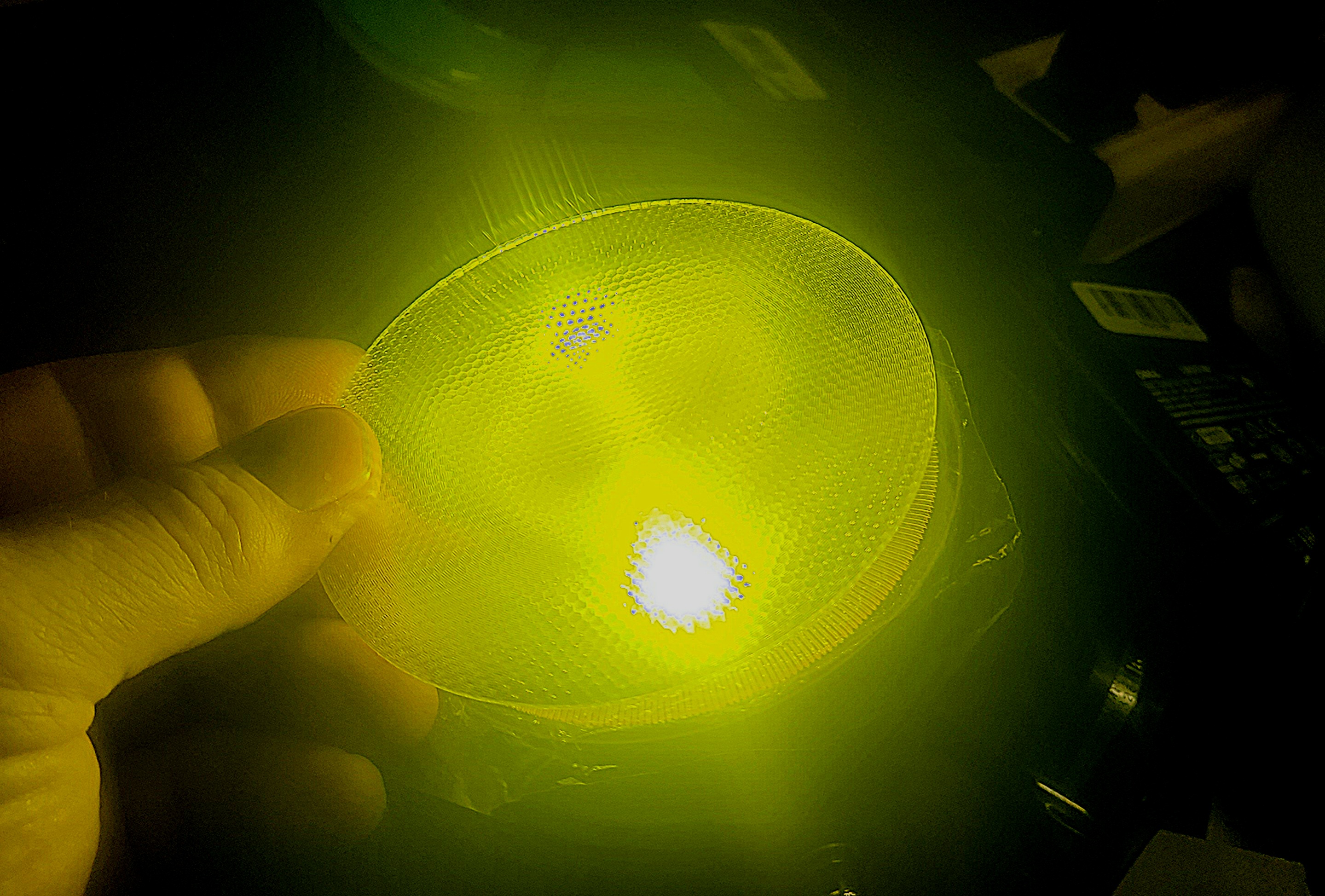
Below: I got this acrylic fresnel lens material which I think will look good in the bezels, with the lights mounted just behind. I don't really need fog lights, so this is just a way to throw some texture on to the light source.
Below: fog light lens and bezel installed. It wasn't difficult to shape the lenses using a heat gun to match the curved profile. The acrylic material is a bit thin and brittle and I do wonder whether it would withstand a bit of gravel fired backward from a tire ahead.

So this feels like satisfactory progress on a number of small jobs, but not like major progress toward completion of the car. Hopefully the pace will pick up a bit this Spring and Summer.


Comments
Post a Comment